|
12-2: The Edit Menu |
|
|
12-2: The Edit Menu |
|
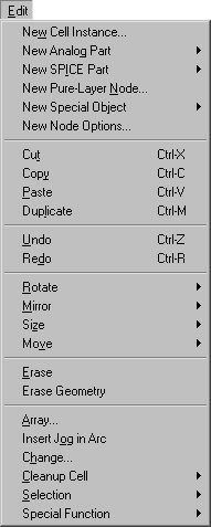
This menu provides all of the basic commands for creating, deleting, and modifying circuitry. Many special objects that do not appear in the component menu on the left can be created with these commands.
This command allows the creation of an instance of a cell. A dialog box will be presented to choose the desired cell, after which you can click in the editing window to create the instance.
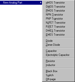 | This command creates a schematic component from the submenu list. Many of these components use values which you will be asked to provide. For example, if you choose the Resistor, a dialog box will request a resistance value to display on that component. |
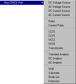 | This command creates a SPICE simulation component from the submenu list. Many of these components use SPICE deck fragments which you will be asked to provide. |
| This command allows the creation of a piece of pure geometry. Pure-layer nodes exist for the purpose of creating unusual layout geometries such as pads or analog circuits. After choosing a node with this command, select a position in the editing window for the node. Initially, pure-layer nodes are square. Other rectangular geometries can be specified with the Size command below. Nonrectangular geometries can be created by using the Outline Edit command below. | 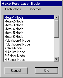 |
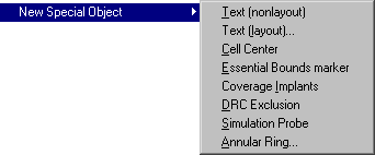 | This command allows the creation of certain special components. |
 | Text (nonlayout) [6-8] | is a free-floating piece of text that merely annotates the circuit. It is not a part of fabrication output. When you click, a piece of text is placed (it is initially the word "text" and is highlighted). |
| Text (layout)... [6-10] | is way to create text that is actual layout. The dialog allows you to specify the text, font, size, scale, and the layer to use (to make the text visible in chip photomicrographs, choose the highest metal layer). |
| Cell Center [3-3] | is a fiduciary mark that, when placed in a cell, defines the center of that cell. This information is used by the editor when creating or moving instances of that cell. Note that once placed, this object can be selected only by using the special select button. | |
| Essential Bounds marker | is a fiduciary mark that, when two or more are placed in a cell, defines the essential area of that cell. Note that once placed, this object can be selected only by using the special select button. | |
| Coverage Implants [7-4] | This command generates pure-layer nodes that cover the implants in the current cell. The nodes are left highlighted so that you can see what has been generated. Previous pure-layer nodes are removed. The new nodes are made "hard to select" to keep them from interfering with normal selection (see Section 2-1). | |
| DRC Exclusion [9-2] | is a node that marks an area to be ignored by the design-rule checkers (Hierarchical and Dracula). See the DRC command in the Tools menu for more on the Dracula interface. | |
| Simulation Probe [10-2] | is a node that marks an area to be tested by simulators. See the DRC command in the Tools menu for more on the Dracula interface. | |
| Annular Ring... [6-10] | presents a dialog for the construction of ring shapes. |
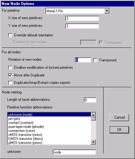
This command presents a dialog that allows default settings to be established for the creation of new nodes. The top section of the dialog lets you set default size and orientation for each primitive node.
The middle section of the dialog contains options that apply to all nodes. The check box "Disallow modification of locked primitives" applies only to primitive node instances in "array" technologies and prevents fixed circuitry from being altered. The check box "Move after Duplicate" allows duplicated objects to be interactively positioned. The check box "Duplicate/Array/Extract copies exports" causes all operations that copy nodes to copy their exports as well. This includes the Duplicate and Array commands of the Edit menu and the Extract Cell Instance command of the Cells menu. Note that export names must be unique, so the copied exports will have their names modified by either changing array indices or by adding "_1", "_2", etc. to the end. Finally, it is possible to set a default orientation of all new nodes.
The bottom section of the dialog allows you to specify node names to be used for the different types of nodes. These names are used when automatically naming nodes during netlisting.
This command copies the currently selected nodes and arcs to the scrap, and then deletes them from the circuit. If you are editing a text window, the selected text is copied and removed. If the Messages window is current, this command copies and removes text from there.
This command copies the currently selected nodes and arcs to the scrap. If you are editing a text window, the selected text is copied. If the Messages window is current, this command copies text from there.
This command copies the nodes and arcs in the scrap back to the currently selected window. If there are nodes or arcs selected when this command is issued, the copied objects are copied ONTO the selected objects, changing them. If you are editing a text window, text from the text scrap is inserted. If the Messages window is current, this command pastes text there.
This command creates a copy of the currently highlighted nodes and arcs. An outline of the duplicated objects attaches to the cursor, and when you click, the objects are placed at that location. If you have disabled "Move after Duplicate" (in the New Node Options... command of the Edit menu) then the duplicated objects are placed immediately without dragging.
This command reverses the last command made to Electric. This will affect ANY command, not just those that change circuitry. Repeated issuing of this command undoes farther back up to a limit of about 30 commands.
This command redoes changes that were undone by the Undo command. Repeated issuing of this command redoes farther up to the last change made.
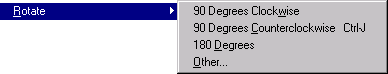 | This command rotates the currently highlighted component. A submenu allows you to rotate in any of the Manhattan orientations, or provide an arbitrary rotation amount. |
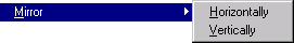 | This command flips the currently highlighted components about their horizontal or vertical centerline, according to the submenu. |
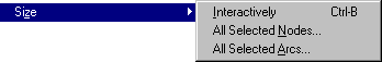 | This command alters the size of the currently highlighted components, according to the submenu. The Interactively option allows graphical adjustment of the currently selected node or arc (the corner farthest from the cursor is anchored and the corner closest to the cursor is pulled to the location of the cursor). The All Selected Nodes and All Selected Arcs options present a dialog for changing the size of the selected nodes or arcs. |
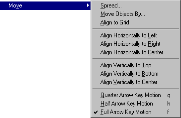 | The subcommands here affect object movement. You can spread a circuit to make room, move objects by specified amounts, align objects to the grid or to each other, and control the amount of movement that arrow keys use. |
This command deletes the currently highlighted objects. Use Undo to restore deleted objects. Note that when a node is erased, all connecting arcs and exports are also erased. However, if a node is deleted that has exactly two arcs, connected as though the node were in the middle of a single arc, then the node and two arcs are replaced with a single arc.
This command deletes all geometry in the currently highlighted area. Arcs that cross into the area will be truncated at the edge of the area. Note that the area is adjusted by the current alignment values (see Section 4-7).
| This command creates multiple copies of the currently highlighted components. A dialog is presented in which the X and Y repeat factors can be specified. Also, alternate rows and columns can be flipped or staggered, and spacing can be specified in many different ways. If array indices are requested, they appear on each copy. | 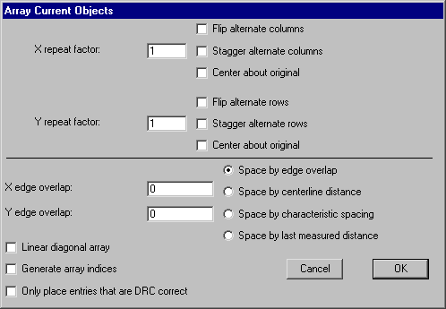 |
This command causes the currently selected arc to have a jog inserted. Press the button and move the cursor to see where the jog will be inserted. Release the button to insert at that location. A jog consists of two pin-nodes, one connected to each half of the arc, and another arc connecting them that runs perpendicular to the original arc. Thus, the jog point allows either half of the wire to be moved laterally, while keeping the parts connected. Inserting two jogs allows an arc to form a "U".
|
This command causes the selected nodes or arcs to be changed to a different type.
A dialog is presented that allows selection of the new type, the scope of the change, and control over how the change is done. | 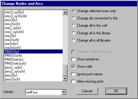 |
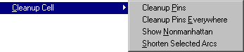 | These commands adjust the current cell so that it is easier to edit. |
| Cleanup Pins [2-2] | This command examines the current cell and removes isolated and irrelevant pins. It also highlights zero-size nodes. |
| Cleanup Pins Everywhere [2-2] | This command examines all cells in the current library and removes isolated and irrelevant pins. It also reports zero-size nodes. |
| Show Nonmanhattan [5-2] | This command identifies all nonmanhattan geometry in the current cell (nonmanhattan geometry is that which is not at right angles with the coordinate axes). In addition, it tells you of other nonmanhattan geometry elsewhere in the database. | |
| Shorten Selected Arcs [5-2] | This command reduces the length of all selected arcs to their minimum, without moving the attached nodes. This works only on arcs that are connected to large ports, and have room to move inside of the port. |
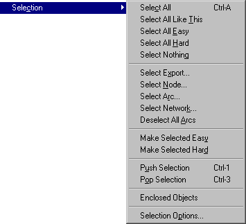 | These commands control selection of objects. |
| Select All [2-1] | This command highlights every node and arc in the current cell. | ||
| Select All Like This [2-1] | This command highlights every node and arc in the current cell that is the same as the currently selected node or arc. | |||
| Select All Easy [2-1] | This command highlights every node and arc in the current cell that is marked as easy-to-select. | |||
| Select All Hard [2-1] | This command highlights every node and arc in the current cell that is not marked easy-to-select. | |||
| Select Nothing [2-1] | This command removes all selection in the current cell. | |||
| Select Export... [3-6] | This command presents a list of ports in the current cell and highlights one. | |||
| Select Node... [2-4] | This command presents a list of nodes in the current cell and highlights one. | |||
| Select Arc... [2-4] | This command presents a list of arcs in the current cell and highlights one. | |||
| Select Network... [6-9] | This command presents a list of networks in the current cell and highlights one. | |||
| Deselect All Arcs [2-1] | This command causes all selected arcs to be deselected. | |||
| Make Selected Easy [2-1] | This command changes all selected objects to be easy-to-select. | |||
| Make Selected Hard [2-1] | This command changes all selected objects so that they are not easy-to-select. | |||
| Push Selection [2-1] | This command saves the currently selected objects on a stack. | |||
| Pop Selection [2-1] | This command restores the previously pushed objects on a stack. | |||
| Enclosed Objects [2-1] | This command changes an area selection into an actual selection of nodes and arcs. If you have used the rectangle select button to define an arbitrary rectangular area on the screen, this command replaces that selection with the actual nodes and arcs in that area. | |||
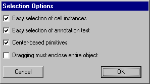
| Selection Options... [2-1] |
|
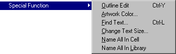 | These commands offers special operations on specific objects. |
| Outline Edit [6-10] | This command allows the currently highlighted node to have its outline manipulated. It works only on certain nodes for which the outline information has meaning. MOS transistors use this information as the centerline of the gate in a serpentine description. Pure-layer nodes use this information to describe their shape. Finally, some primitives from the Artwork technology can use this information to describe their shape. Once this command is issued, the buttons are redefined to apply specifically to outline editing. The selection button selects and moves a point on the outline, and the creation button creates a new point. Also, the Erase, Rotate, and Mirror commands of this menu change meaning when editing outlines. Use the Get Outline Info command of the Info menu to see outline coordinates. To terminate outline editing, this menu entry changes to Exit Outline Edit which, when reissued, restores the commands and mouse buttons. | ||
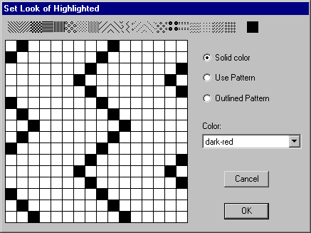
| Artwork Color... [7-7] |
| |||
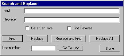
| Find Text... [4-10] |
| |||
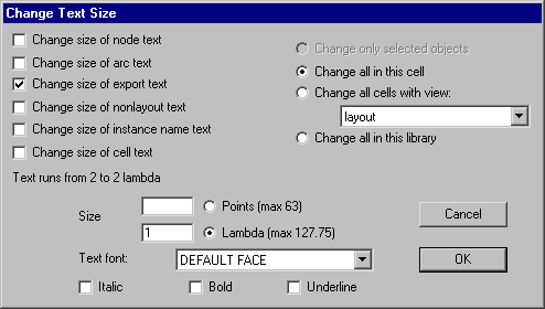
| Change Text Size... [6-8] |
This command presents a dialog for changing the size of text objects.
| |||
| Name All In Cell [2-4] | This command names every node and arc in the current cell. The names do not appear, but are present for netlisters and debugging. (Note that netlisters that need names do this automatically.) | |||
| Name All In Library [2-4] | This command names every node and arc in the current library. The names do not appear, but are present for netlisters and debugging. (Note that netlisters that need names do this automatically.) |
 |
Previous |  |
Table of Contents | Next |  |