 |
6-8: Text |
|
|
6-8: Text |
|
There are a number of ways to place text in a circuit.
The only category of text in the above list that is not selectable is the text that is integral to a node's graphics (i.e. the Flip-Flop). For the rest, you can select and manipulate the text just as you would the object on which the text resides. (Note that port names on cell instances are not selectable: instead, select their export name inside of the cell definition.)
Certain types of text are not easily selectable. This is a feature that prevents accidental selection of unwanted text. For such pieces of text, the only way to select them is to use the special select button. By default, the name of an unexpanded cell instance requires this button. However, you can also request that names on nodes and arcs (annotation text) also be difficult to select by unchecking "Easy selection of annotation text" in the Selection Options... subcommand of the Selection command of the Edit menu.
| All text is attached to its node or arc at a grab-point. This is the one point on the text that never moves, regardless of the size of the text. The highlighting of selected text varies according to the grab-point. Typically, the highlighting consists of an "X" through the text. This indicates that the grab-point is in the center. If a "U" is drawn in any of four orientations, it indicates that the grab-point is on the side and that the text grows out of the opened end. If an "L" is drawn in any of four orientations, it indicates that the grab-point is in a corner. Finally, the text may be drawn with an "X" but also have four lines that indicate a box at the object edge. This is centered text that clips to the size of its attached object (it is boxed). | 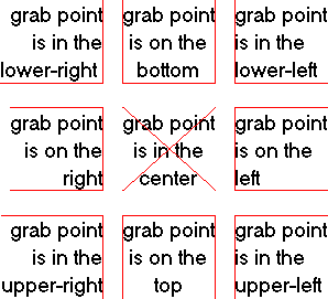 |
Like nodes and arcs, text can be moved simply by clicking and dragging. It can be erased with the Erase command of the Edit menu.
There are two ways to change the actual text: in-place editing or with a dialog. In-place editing is done by double-clicking on the text. After the double-click, all of the text is selected. Portions of the text can be selected by clicking over it. To insert or replace text, simply type. When done editing, click away from the text to end the editing mode.
| Dialog control of text is done by using the Get Info command of the Info menu. This dialog allows modification of the text, size, font, style, grab-point, rotation, and even the offset of the grab-point from the attached node or arc. Note that the offset is always relative to the center of the attached object. The size of text can be absolute (given in "points") or relative (given in lambda units). The font of text can use the default face or any font installed on your system. The style of text can be any combination of Italic, Bold, or Underline. Text rotation can be in 90-degree increments only. You can set the units to any electrical type (capacitance, resistance, etc.) See section Section 7-2 for more on these units. The "Language" option allows the text to be code in an interpretive language, in which case, the evaluation of that code is displayed. (see Section 11-1 for more on languages). You can choose to show the text value, the name of the piece of text, or both. The little arrows next to the grab-point options show where the point of attachment lies on the text. | 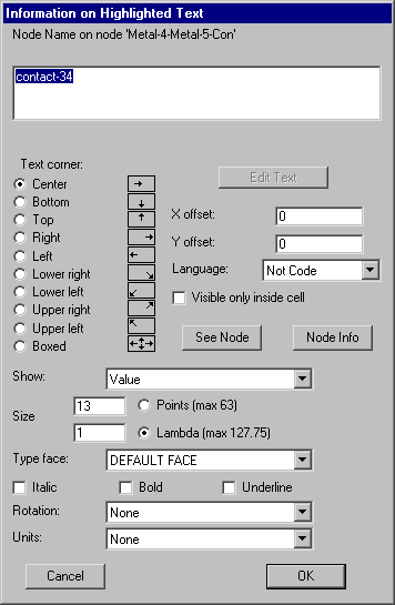 |
If the text contains more than 1 line, then the only way to change it is to click on the "Edit Text" button, which closes the dialog and enters in-place editing mode. The "See Arc" button highlights the arc on which the text is attached (the button is "See Node" if the text is on a node). Similarly, the "Arc Info" (or "Node Info") button brings up the Get Info dialog for that object. The checkbox "Visible only inside cell" requests that the text not be drawn when an instance of the cell is examined. In addition, for text objects (those created with the Text (nonlayout) subcommand of the New Special Object command of the Edit menu) the location of the text will not affect the bounding box of the cell. This means that the text can be placed arbitrarily far outside of the actual layout, and it will not affect the hierarchy.
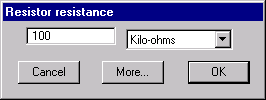 | For special pieces of text that the system understands, you may get a customized dialog when you double-click. For example, if you double-click over the resistance value of a resistor, a special dialog will appear to set the resistance. To change other information, use the "More..." button to see the general dialog. |
| The Change Text Size... subcommand of the Special Function command of the Edit menu allows you to change the size, face, and style of any text object. You can choose which of the 6 classes of text you wish to change, and you can choose whether to make the changes only on selected objects, in the current cell, in all cells of a particular view, or everywhere. | 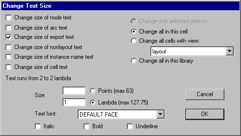 |
To change the default size and grab-point of all new text, use the Text Options... command of the Windows menu. The top part of the dialog lets you set the default size, face, and style of text that will appear in different locations (on cell instances, on nonlayout text, on exports, on nodes, and on arcs). Nonlayout text is the freestanding text that is created with the Text (nonlayout) subcommand of the New Special Object command of the Edit menu.
|
The center section of the dialog has two unrelated controls. The field labeled "Text editor" allows you to choose which style of text editing to use when working with large amounts of text (see Section 4-10 for more on text windows). The "New text visible only inside cell" checkbox requests that nonlayout text objects be drawn only when inside of the cell, and not when instances of the cell are expanded. | 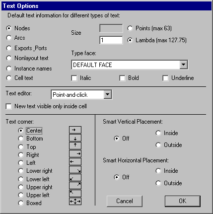 |
The lower-left part of the dialog lets you set the grab-point of subsequently created text. The lower-right part of the dialog controls "smart placement" of text, which adjusts the grab point according to the environment of the text. This currently applies only to export names, which are placed relative to the arc connecting to the exported node. For example, if a node on the left end of a wire is has an export, and the "Smart Horizontal Placement" is set to "Inside", then the export text will attach on the left side, causing the label to appear inside of the wire.
You can place arbitrary text attributes on nearly any part of the circuit by using the Define... subcommand of the Attributes command of the Info menu.
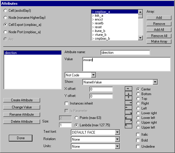
Attributes can be placed on these objects (selected in the upper-left):
Just below the attribute's value is a field that reads "Not Code". This can be changed to one of the interpretive languages in Electric. When this happens, the attribute value is treated as code that is sent to that interpreter. Then, the true value of the attribute is the evaluation of that code. For example, if the value of an attribute is "(+ 3 5)" and the attribute is set to be LISP code, then the LISP interpreter will be invoked, and the attribute will actually be "8". For more on interpretive languages, see Section 11-1.
You can change the type of unit by using the popup menu on the bottom (choices are capacitance, resistance, inductance, current, voltage, or distance). See section Section 7-2 for more on these units.
For attributes on cells or exports, you can request that they be inheritable with the "Instances inherit" checkbox. When this is checked, newly created instances of the cell will have copies of this attribute on them. Using this scheme, an attribute can be considered to be a parameter, where values set on the instances are used inside of the cell. The "Is Parameter" checkbox should be selected in this case (note that the proper way to create parameters is with the Cell Parameters... subcommand, not this dialog). If you check "Visible only inside cell" in the attribute's Get Info dialog, then the inherited attributes will not be displayed.
It is often desirable to have attribute values that have unique names. If the value of an inherited attribute has "++" in it, then the number before it will be incremented after inheritance. Similarly, a "--" indicates that the number be decremented after inheritance. This allows an inherited attribute to be unique with each inheritance.
| Another way to create attributes with unique values is to place a "?" in the attribute value and then use the Enumerate... subcommand on the attribute name. This command finds all occurrences of that attribute, and replaces the "?" with a unique numeric value. | 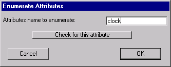 |
If you create a new inheritable attribute and wish to propagate it to existing instances, select the instance and use the Update Inheritance subcommand of the Attributes command of the Info menu. To propagate attributes to all instances, use Update Inheritance All Libraries.
You can control the way that an attribute is displayed in the circuit by selecting the appropriate entry in the "Show:" popup. You can request that various combinations of the attribute's name, value, and inherited value be displayed. When an attribute is shown, additional information is relevant. The grab-point of the text can be chosen from the list in the lower-right. The X and Y offset of the text from the attached object can be specified. The size of the text can be specified in relative or absolute units. The font of the text can be chosen from the popup list. The style of the text can be any combination of Italic, Bold, or Underline. You can even specify the orientation of the text, in 90-degree increments.
When there are too many visible attributes, the display can become cluttered. Use the Layer Visibility command of the Windows menu to control the text. (attributes on nodes are controlled by the "Node Text" checkbox; those on arcs with the "Arc Text" checkbox, etc.)
Special buttons exist in the upper-right for applying changes to many ports or exports. By using the "Add", "Remove", "Add All", or "Remove All" buttons, you can select a subset of names (those with a ">" are selected). Then, by using the "Make Array" button, the currently selected attribute is copied to all selected locations.
The "Done" button terminates this dialog. Note that there is no "Cancel" button: this dialog makes changes as they are entered.
| To help organize the attributes in a circuit, the Attribute Report... subcommand of the Attributes command of the Info menu lists every occurrence of a particular attribute name. You can also request that this command dump the report to a disk file. | 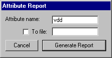 |
Parameters are special types of attributes that communicate information down the hierarchy, from a cell instance to its contents. One example of the use of cell parameters is in the SPICE primitives where user-defined values (such as voltage) are communicated into the icon for generation in the SPICE deck (see Section 9-4).
Another use of cell parameters is to parameterize the size of a transistor in a schematic (or to parameterize the scalable layout transistors in the MOSIS CMOS technology, see Section 7-5) The transistor width and length can be defined in terms of the parameter value, allowing a single cell to take on many different forms. By combining these parameters with the interpretive language facility, an arbitrary mathematical expression can be placed on the transistor which combines parameter values to form the exact transistor size (see Section 11-1 for more on interpretive languages).
Parameters are created with the Cell Parameters... subcommand of the Attributes command of the Info menu.
| The dialog shows the existing parameters, and allows you to create and delete them. Each parameter has a default value that will be used if no instance value can be found. You can also set the type of electrical unit that this parameter describes (capacitance, cesistance, etc.) See section Section 7-2 for more on these units. | 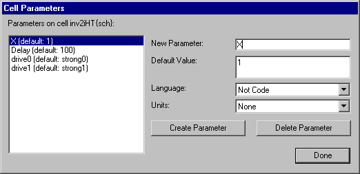 |
Cell parameters are implemented as inheritable attributes. Inheritble attributes are automatically placed on each newly-created node instance (thus, they are inherited from the prototype to the instance). Inside of the cell, the parameter is shown with its name, default value, and actual value from up the hierarchy. For example, the parameter defined in the above dialog will appear in the cell as the string "Strength=?;def=2". This means that the actual value from up the hierarchy is not known ("?") but the default is 2.
When an instance of this cell is created, a new attribute will be placed on it with the default value. In this example, the instance will have the text "Strength=2" on it. Since this attribute is separate from the defining one in the cell, you can edit and change its value. Besides clicking on the text to edit the value, you can also see all parameters on a node by selecting the "Parameters" button in the node's Get Info dialog. Once an instance is created with a parameter value, you can descend the hierarchy from that instance and see the actual parameter value inside of the cell. So, if you changed the instance text to read "Strength=15", then descending into the cell will show the string "Strength=15;def=2".
A parameter, defined in a cell, always appears on every instance of that cell. If you have added a parameter after creating instances, use the Update Inheritance or Update Inheritance All Libraries commands.
In schematics, the location of a parameter on an icon is determined by the location of that parameter on the sample icon, inside of the schematic cell. If you make changes to the parameter locations on the sample icon, you can propagate those changes to icon instances with the commands Update Locations (updates only the selected icon instances) or Update Locations All Libraries (updates all icon instances).
If you do not wish to see a parameter's text on any instance, select the parameter text inside of the cell, use Get Info from the Info menu, and check "Visible only inside cell". To override the visibility of cell parameters on an instance, use the See All Parameters on Node, Hide All Parameters on Node, and Default Parameter Visibility subcommands of the Attributes command of the Info menu. These commands make all parameters visible, invisible, or back to their default as specified in the cell.
 |
Previous |  |
Table of Contents | Next |  |