 |
4-7: Grids and Alignment |
|
|
4-7: Grids and Alignment |
|
The Toggle Grid command of the Windows menu turns the grid display on and off. The grid consists of dots at every grid unit, and bolder dots every 10 units, but both of these distances are settable.
Initially, the grid dots are spaced 1 lambda unit apart. The term lambda indicates a generic spacing unit that can be scaled independently of the actual layout. For example, in the MOSIS CMOS technology, the value of lambda is 0.2 microns, as shown in the status area under the heading "LAMBDA". When the grid is displayed, the dots are therefore 0.2 microns apart. For more information on lambda, Section 7-2.
Note that the grid display changes as you zoom in and out. When zoomed too far out to show all of the dots, only the bolder dots are shown. When zoomed too far out to show even the bolder dots, the grid is not displayed. However, the fact that the grid should be on is remembered, so it reappears when you zoom back in.
The location of the grid dots is always aligned with the "grab point" of the cell. Because this is normally the lower-left corner, the dots will always pass through that point. If, however, a Cell-Center node (named "Facet-Center" for historical reasons) is placed in the cell (with the Cell Center subcommand of the New Special Object command of the Edit menu) then the grid dots will always pass through that point.
| The Grid Options... command presents a dialog in which grid spacing may be set. You can change the grid spacing for the current window, and also set a default grid spacing to be used in new windows. | 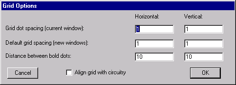 |
It is possible to change the horizontal and vertical grid dot spacings. You can also change number of grid dots between bold ones. Finally, you can choose whether or not to align the grid with the circuitry. When aligned, the dots are drawn so that they always fall on the "grab point" (normally the lower-left corner of the circuitry). When not aligned, the dots are drawn in the same location, regardless of the circuitry.
The grid spacing is used by arrow keys when they move objects (see Section 2-4 for more on arrow key motion).
When moving or creating circuitry, the cursor location is snapped to a grid so that editing is cleaner. This snapping is controlled by the alignment options (which are not necessarily the same as the grid options).
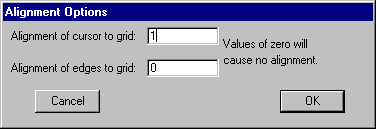 |
The Alignment Options... command presents a dialog in which alignment values may be set. For example, if the grid spacing is 2x3, and the alignment is 0.5, then there are up to six different positions for placement inside a displayed grid rectangle. |
A special grid setting is the alignment of edges, which initially is set to zero (no alignment). This alignment affects the edges of nodes and arcs (as opposed to their lower-left corner, where the grab-point resides). For example, if a 3 lambda wide wire is drawn into a 4x4 contact, the default will be to center that wire, which will place the edges of the wire on half-lambda grid locations. If, however, the edge alignment is set to 1 lambda, then that wire will be forced to one side of the contact so that its edges align. Note that it is not always possible to align edges properly, so you should always check your geometry if you insist on this feature.
The Align to Grid subcommand of the Move command of the Edit menu cleans up the selected objects by moving them to aligned coordinates. This is useful for circuitry that has been imported from external sources, and needs to be placed cleanly for further editing.
It is often the case that a collection of objects should line-up uniformly. The subcommands of the Move command of the Edit menu offer six possible ways to do this.
The subcommand Align Horizontally to Left (and Align Horizontally to Right) moves all of the objects so that their left edge (or right edge) is moved to the leftmost (or rightmost) location of those objects. The subcommand Align Horizontally to Center moves all of the objects so that their X center is at the location of the X center coordinate of those objects.
The subcommand Align Vertically to Top (and Align Vertically to Bottom) moves all of the objects so that their top edge (or bottom edge) is moved to the topmost (or bottommost) location of those objects. The subcommand Align Vertically to Center moves all of the objects so that their Y center is at the location of the Y center coordinate of those objects.
As an aid to precise alignment, the Show Cursor Coordinates command of the Info menu causes the X and Y cursor positions to be continuously displayed in the status area. This information appears where the Technology and Lambda used to be. To restore display of Technology and Lambda values, uncheck this menu entry.
If you wish to find the distance between any two points on the display, use the Measure Distance command of the Info menu. After this command is issued, click in the circuit to set the "starting point". Then click repeatedly in the circuit to define the "ending point" and see the measured distance. To end distance measurement, issue the command again. The measured distance can be used by the Array... command to specify spacing (see Section 6-4).
 |
Previous |  |
Table of Contents | Next |  |