 |
4-6: Colors |
|
|
4-6: Colors |
|
The subcommands in the Color Options command of the Windows menu control the appearance of individual layers in the editing window. Before explaining these commands, it is useful to understand the distinction between transparent and opaque layers in Electric.
On color displays, up to five of the layers can be transparent, meaning that when they overlap each other, it is possible to see all of them. Typically, the most commonly used layers are transparent because it is both faster to draw and clearer to distinguish. The remaining layers in a technology are opaque, meaning that when drawn, they completely obscure anything underneath. These layers typically have stipple patterns so that they do not cover all of the bits. In this way, the opaque layers can combine without obscuring the display. Because stipple patterns are slower to draw, and because opaque color does obscure, the less common layers are drawn in this style. When editing colors, the opaque layers have only one color, whereas the transparent layers have up to 16 different colors, considering their interaction with other transparent layers.
The first Color Options subcommand is Edit Colors..., which presents a color mixing dialog. The bottom half of the dialog shows a set of 16 colors that can be edited. A popup menu allows different sets of 16 to be selected. The choices are:
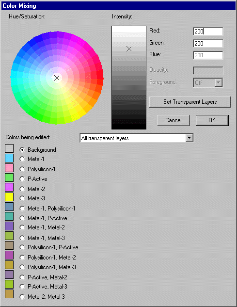
To edit a color, choose a particular color button and edit its value in using controls in the top half of the dialog. The mixing palette consists of a hue/saturation wheel and an intensity slider. You can also type numeric values for the Red, Green, and Blue. For printable colors, there is also an Opacity (1.0 if opaque, smaller values to control blending with other colors) and a Foreground factor ("On" if this layer can merge with others behind it).
When changing the background color, note that it must contrast with both the highlight color and the inverse of the highlight color (the inverse is black in the default settings).
The "Set Transparent layers" button helps with the tedious task of defining all combinations of transparent colors. Because there are 5 transparent layers, it is necessary to define 32 different combinations of these colors. Instead, you can simply select the 5 transparent colors and the background color and then use this button to compute the remaining 26 combinations.
| Another command for color manipulation is Highlight Layer..., which allows you to highlight a single layer. The command changes the colors so that all other layers are dimmer (actually 20% less saturated). The selected layer is thus highlighted on the display. Choose the "None" button to restore default colors. This command works as you click in the dialog, so that you can easily preview the circuit, one layer at a time. It only works on the transparent layers. | 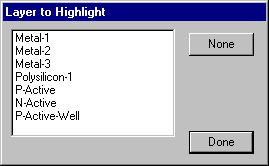 |
The final color subcommands are Restore Default Colors, which resets all colors to the default set for the current technology, Black Background Colors which resets all colors to the default for the current technology but with a black background, and White Background Colors which resets all colors to the default for the current technology but with a white background.
| Besides editing colors, it is also possible to assign them to layers and to edit each layer's stipple patterns. The Layer Display Options... command of the Windows menu gives you this facility. Although many layers are drawn with solid colors on a color display, they all have patterns that are used for hardcopy output. The dialog that appears with this command allows the patterns to be edited, provides a set of predefined patterns, and allows you to determine whether or not the pattern is used on the display. You also have the option of outlining stippled polygons with a solid line. Finally, you can assign any transparent or opaque color to a layer. | 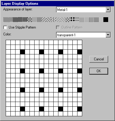 |
 |
Previous |  |
Table of Contents | Next |  |