 |
2-4: Circuit Modification |
|
|
2-4: Circuit Modification |
|
Components can be moved by clicking on them with the selection button and then dragging them around while keeping the button pressed. During the drag, the new location of the components will be shown (as well as the amount of motion), and once the button is released the circuitry will be moved.
Another way to move objects is to use the arrow keys. When a node or arc is selected, each press of an arrow key moves that object by one grid unit. If the shift key or the menu key is held (the menu key is Command on Macs, Control on Windows and UNIX), then the arrow keys move the object by a block of grid units. A block of grid units is defined in the Grid Options dialog to be the distance between bold dots in the grid, initially 10. If you hold both the shift key and the menu key, then the distance moved will be a block squared (i.e. initially 100).
The distance that the arrow keys move is also affected by the subcommands of the Move command of the Edit menu. The Quarter Arrow Key Motion command causes the amount to be quartered (so unshifted arrow keys will move by a quarter lambda). The Half Arrow Key Motion command causes the amount to be halved (so unshifted arrow keys will move by a half lambda). The Full Arrow Key Motion command causes the amount to be full (so unshifted arrow keys will move by lambda). Note that these menu items are attached to the "q", "h", and "f" keys.
To move objects along only one line (just horizontally or vertically but not both), hold the Control key down during motion. Note that holding the Control key down before clicking will change the nature of the mouse action, so you must click first, and then press Control. When editing schematics, this will constrain objects to movement along 45 degree angles.
When arcs are moved by a large amount, they cause the connecting nodes to move with them. However, for small arc motion, the arc may shift within its ports. This can only happen if the port has nonzero area and if the arc has the slidable constraint (shown with the letter "S" when highlighted). These constraints are discussed in greater detail in Section 5-2.
Another way to move a node is to use the Get Info command of the Info menu, and type new X and Y positions. This dialog allows other modifications to be made as well (orientation, etc.)
| The dialog shows the location of the grab-point of the node, which may be in any number of positions (see Section 2-2). Note that the default unit for typed values is lambda, unless another unit is explicitly mentioned (for more information on lambda, Section 7-2). | 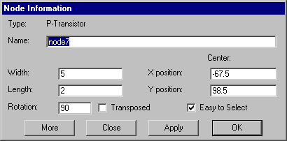 |
The dialog also has a field for the node's name. This name is not related to network information, but it can be used for identification. If a schematic node is given an arrayed name (such as "and[0:3]") then it indicates that the node is arrayed that many times. Nodes (and arcs) can automatically be given names with the Name All In Cell and Name All In Library subcommands of the Special Function command of the Edit menu. When naming nodes, the prefix used depends on the node function (see the New Node Options... command of the Edit menu).
Note the "Easy to Select" checkbox in this dialog. If you uncheck it, you will have to use the special select button to select the node in the future. This feature allows you to eliminate pieces of circuitry from active editing.
This dialog is modeless: it can remain on the screen while other editing is being done. If a different node is selected, the dialog updates to show that node's information. The "Apply" button changes the selected node to match the new values typed into the dialog.
The Get Info dialog can also expand to show more information. When the "More" button is clicked, it grows to full size as shown. To make the dialog default to full size, use the General Options... subcommand of the User Interface command of the Info menu and check "Expandable dialogs default to fullsize".
The full size Get Info dialog has many new controls,
which vary according to the type of node selected:
| 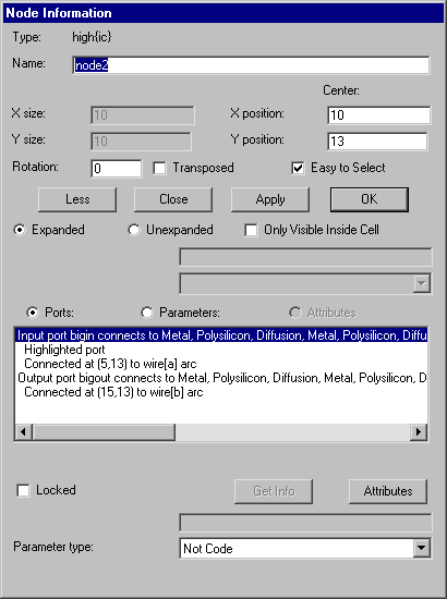 |
By default, a list of the node's ports is shown, including any exports, connections, and highlight details. If the "Attributes" button is selected, the list shows the attributes on the node. If the "Parameters" button is selected, the list shows the parameters on the node Parameters are similar to attributes: they both are fields on the node. However, parameters are also fields inside of the defining cell. When "Attributes" or "Parameters" are selected, the entries in the list let you modify individual values, and the "Attributes" button brings up an extended dialog for them.
If many objects are selected, you can move them by a specific distance with the Move Objects By... subcommand of the Move command of the Edit menu.
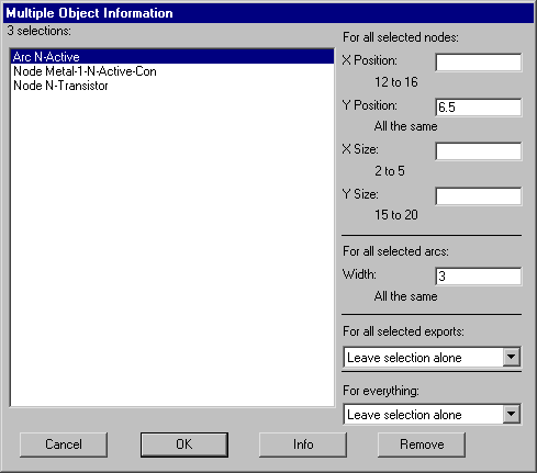 | If many nodes are selected, the Get Info command will list all of them, and allow position and size changes to be made at once to each in the group. If a position and size value appears in the dialog, it means that this value is the same on every selected node. If the field is blank, it means that there are different values. |
Changes are only made in the fields where you type a value. To see the full "Get Info" dialog for the selected node, click on the "Info" button. To remove an item from the list (not the circuit, just this list) use the "Remove" button. If only two objects are selected, this dialog shows the distance between their centers.
The multi-object Get Info dialog also allows you to change selection style with the "For everything:" popup (see Section 2-1 for more on selection styles). When many exports are selected, the dialog allows you to change their characteristics with the "For all selected exports:" popup (see Section 3-6 for more on exports).
 |
Previous |  |
Table of Contents | Next |  |