|
12-8: The Info Menu |
|
|
12-8: The Info Menu |
|
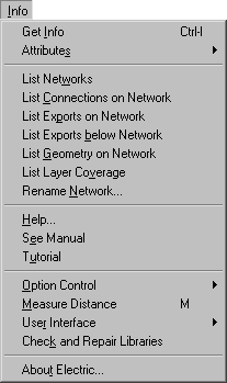
This menu provides a collection of information gathering facilities. The most useful is Get Info which describes the currently highlighted object. Other informational commands exist to describe the circuit. Help... and Tutorial functions are available. Also, default node and arc creation information can be set.
This command presents a dialog that shows information and allows modification of the currently highlighted node, arc, export, or text.
| When a single node is highlighted, this command presents the dialog shown here. This dialog is modeless and can remain on the screen while other editing is done. It always shows information about the currently selected node. The dialog can grow to include more information if the "More" button is clicked. | 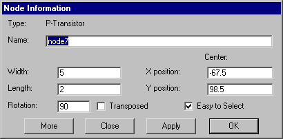 |
| When a single arc is highlighted, this command presents the dialog shown here. All of the options in the Arc menu may be set here. The "Name" field defines a network name for this arc and all others electrically connected to it. You can highlight the nodes on either end of the arc with the "See" buttons, and get information about them with the "Info" buttons. If you uncheck the "Easy to Select" button, you will have to use the special select button to select it in the future. The "Attributes" button lets you edit special attributes on the arc. | 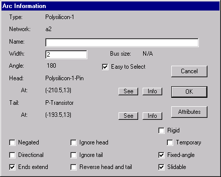 |
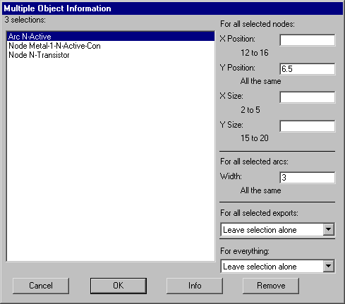 | When multiple objects are selected, the dialog lists them and lets you do simple operations on all of them (position, size, width). If two objects are highlighted with selection and toggle select buttons, this dialog also shows the distance between their centers. A popup entry allows you to make the selected objects easy or hard to select (see Section 2-1). |
| When an export's name is highlighted, this command presents the dialog shown here. The characteristics of the export can be set; the size, font, style, and rotation of the export name can be set; and the location of the export name relative to the export center can be set. The "Attributes" button lets you edit special attributes on the export. | 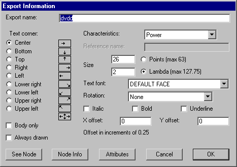 |
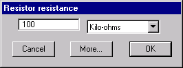 | When special pieces of text are highlighted, this command presents a customized dialog for that value. For example, when the resistance value on a resistor is selected, this dialog is used. |
| When any other text is highlighted, this command presents the dialog shown here. Many factors can be set, including the size, the location relative to the grab-point, and whether to show the name of the attribute that holds this text. | 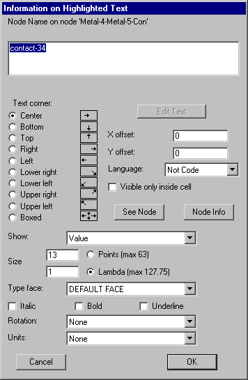 |
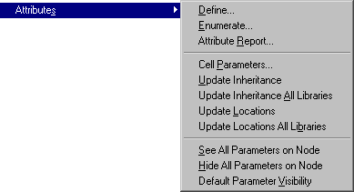 | The subcommands of this command control additional attributes which can be placed on objects. |
 | Define... |
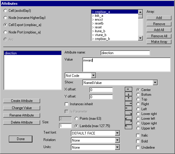
This command allows additional attributes to be placed onto parts of the circuit.
The five possible locations for attributes are selectable in the upper-left.
You can place attributes on (1) the current cell, (2) the currently selected node,
(3) exports on the current cell, (4) ports on the currently selected node,
and (5) the currently selected arc.
When you choose the object on which attributes are being set,
you will see a list of attributes in the lower-left.
If you have chosen port or export attributes,
a list of port/export names is shown in the upper-right.
 | ||
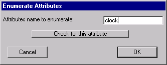
| Enumerate... |
| |||
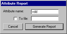
| Attribute Report... |
| |||
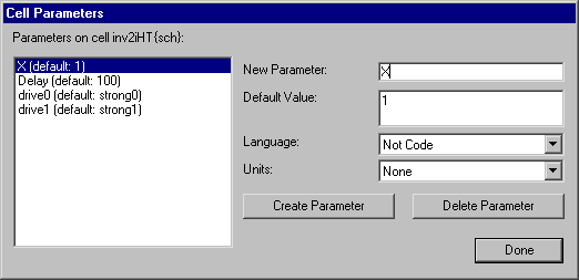
| Cell Parameters |
This command creates parameters in the current cell.
Parameters are attributes inside the cell that get copied to all instances of the cell.
 | |||
| Update Inheritance | This requests that the selected nodes inherit all inheritable attributes. Those attributes that have already been inherited will not be altered; only new inheritable attributes will be brought from the prototypes to the instances. | |||
| Update Inheritance All Libraries | This requests that all nodes inherit all inheritable attributes. Those attributes that have already been inherited will not be altered; only new inheritable attributes will be brought from the prototypes to the instances. | |||
| Update Locations | This requests that the selected nodes adjust the location of all inheritable attributes to match the attribute locations on their example icon (in the schematic). | |||
| Update Locations All Libraries | This requests that all nodes adjust the location of inheritable attributes to match the attribute locations on their example icon (in the schematic). | |||
| See All Parameters on Node | This command sets all parameters on the selected nodes to be visible. | |||
| Hide All Parameters on Node | This command sets all parameters on the selected nodes to be invisible. | |||
| Default Parameter Visibility | This command sets all parameters on the selected nodes to be visible or invisible, according to their original definition in the prototype cell. |
This command lists the named networks in the current cell. Networks can be given names by selecting an arc on the network, using the Get Info command above, and filling in the "Name" field.
This command lists the active components connected to the current network. The current network is the collection of nodes and arcs connected to the currently highlighted objects. If a node is highlighted that has multiple networks on it, the particular port that is highlighted on the node determines the network.
This command lists all exports on the current network, at all levels of the circuit hierarchy, above and below the current cell. It is useful when checking to see that an export is named uniformly throughout the chip, because all export names are shown.
This command lists the exports on the current network and in all cells below this in the hierarchy.
This command computes the geometry connected to the current network and reports the area and perimeter of all connected layers. Only geometry at the current and lower levels of hierarchy are considered.
This command computes, for each layer, the percentage of the cell that is covered by that layer. This is useful because certain fabrication lines insist on a minimum amount of area for each layer.
This command presents a list of networks in the current cell and lets you rename them.
This command provides information about the use of Electric. A dialog helps to select the subject.
This command displays the user's manual in a browser.
This command loads a tutorial package that provides some examples of use.
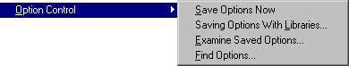 | The subcommands of this command control how options, set by the many Option commands, are saved. |
| Save Options Now | This command requests that the current set of options be saved now, rather than waiting for the program to exit. | ||
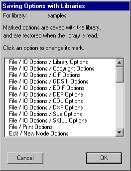
| Saving Options With Libraries... |
| |||
| Examine Saved Options... | This command shows all options that are part of the saved options, indicating those that have been changed this session. | |||
| Find Options... | This command helps you find an option. It presents a list of all options and lets you search for a keyword. |
This command allows you to measure the distance between any two points on the display. After issuing it, click in the circuit to set the "starting point". Then click repeatedly in the circuit to define the "ending point" and see the measured distance. To end distance measurement, use this command again. The measured distance can be used by the Array... command to specify spacing. Note that this command is bound to the "M" key (shift-M).
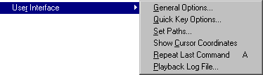 | The subcommands of this command control various aspects of the user interface. |
| General Options... [9-1] | This command presents a dialog with options that pertain to the overall running of the system. |
| Quick Key Options... [1-9] | This allows you to rebind the quick keys (the keys that invoke menu entries). | |
| Set Paths... | This lets you examine and modify the current directory in which library files can be found. | |
| Show Cursor Coordinates [4-7] | This causes the cursor coordinates to be continuously displayed in the status area (they are shown where the Technology and Lambda information used to be). Issue the command again to remove coordinate display. | |
| Repeat Last Command [1-9] | This causes the last command that was issued to be issued again. It only applies where sensible. If the last command required a dialog, that dialog is brought back, but the values entered into it must be reentered. | |
| Playback Log File... [6-12] | This replays a session log file, which is useful for recreating lost circuitry after a crash. Electric can usually detect when a crash has occurred, so you should not normally need to issue this command. |
This command examines the database for inconsistencies and repairs them whenever possible. Given that Electric is a stable, working program, this command should not uncover any problems. If, however, the system is acting strangely, try saving your library and running this.
This command displays a dialog with information about the current version of Electric.
 |
Previous |  |
Table of Contents | Next |  |