
9-4-2: Verilog
Chapter 9: Tools
|
9-4: Simulation Interface 9-4-2: Verilog |
|
Electric can produce input decks for Verilog simulation with Write Verilog Deck... command (in menu Tools / Simulation (Verilog)). For VerilogA format, use the Write VerilogA Deck... command. After this has been done, you must run Verilog externally to produce a ".dump" file. Note that the Electric distribution does not come with a Verilog simulator: you must obtain it separately.
After running a Verilog simulation, you can read the ".dump" file into Electric and display it in a waveform window. This is done with the Plot Simulation Output, Choose File... command (in menu Tools / Simulation (Verilog)). You can also use the Plot Simulation Output, Guess File command if the cell name and file name are the same. The Verilog simulation information is then shown in a digital waveform window (see Section 4-11 for more). Electric also understands the output of Modelsim and can plot it.
Before generating Verilog decks, it is possible to annotate circuits with additional Verilog text that will be included in the deck. To add Verilog code to this cell, select "Verilog Code" under the "Misc." entry in the component menu of the side bar. To add a Verilog declaration in this cell, select "Verilog Declaration" under the "Misc." entry in the component menu. To add a Verilog parameter to this cell, select "Verilog Parameter" under the "Misc." entry in the component menu. To add external Verilog code, outside of this cell, select "Verilog External Code" under the "Misc." entry in the component menu. These pieces of text can be manipulated like any other text object (see Section 6-8-1 on text). For an example of Verilog layout and code, look at the cell "tool-SimulateVERILOG" in the Samples library (get this library with the Load Sample Cells Library command, in menu Help).
Additional control of Verilog deck generation is accomplished with the Verilog Preferences (in menu File / Preferences..., "Tools" section, "Verilog" tab).
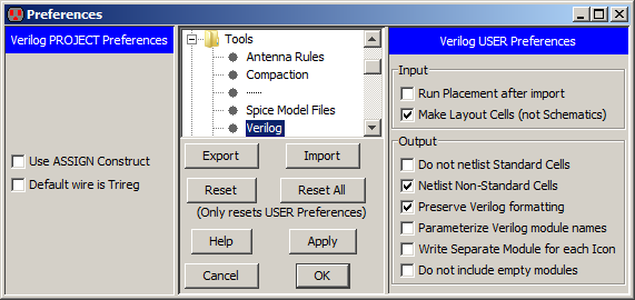
The left side is the Verilog Project Preferences which has two controls:
Another property that can be assigned to transistors is their strength. The Weak command (in menu Tools / Simulation (Verilog) / Transistor Strength) sets the transistor to be weak. The Normal command restores the transistor to be normal strength.
Still more control of Verilog deck generation is accomplished with the Verilog User Preferences in the right side of the dialog.
A final set of Verilog controls can be found in the Verilog Model Files Preferences (in menu File / Preferences..., "Tools" section, "Verilog Model Files" tab). The Verilog Model Files Preferences dialog lets you control how each cell is represented in the Verilog.

The default is to construct the Verilog from the actual cell contents. If there is an equivalent layout cell, it can be used (instead of the schematic). You can also choose to use the "Verilog" view, which contains Verilog text for that cell. Finally, you can request that an external model file be used. These choices allow you to create your own definitions in situations where the derived Verilog would be too complex or otherwise incorrect.
 |
Previous |  |
Table of Contents | Next |  |