
9-4-3: Spice
Chapter 9: Tools
|
9-4: Simulation Interface 9-4-3: Spice |
|
Electric can produce input decks for Spice simulation with the Write Spice Deck... command (in menu Tools / Simulation (Spice)). Since there are may formats of Spice output, you must first set the "Spice Engine" field of the Spice/CDL Preferences (in menu File / Preferences..., "Tools" section, "Spice/CDL" tab). After the Spice deck has been written, you must run Spice externally to produce a simulation output file. Note that the Electric distribution does not come with a Spice simulator: you must obtain it separately.
After Spice has finished running, use the Plot Simulation Output, Guess File command (in menu Tools / Simulation (Spice)) to read the Spice output and plot the waveforms. If the file cannot be guessed from the cell name, you can use Plot Simulation Output, Choose File..., to select the desired Spice output file. The Spice simulation information is shown in a waveform window (see Section 4-11 for more).
|
There are many powerful facilities for running Spice with Electric.
The example shown here illustrates some of these facilities.
This example is available in the Samples library as cell "tool-SimulateSpice"
(you can read the library with the Load Sample Cells Library command, in menu Help).
All input values to Spice are controlled with special nodes, found in the "Spice" component menu entry. Note that the first time any Spice node is placed, the library of Spice parts is loaded into Electric, so there may be a delay. | 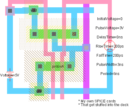 |
The Spice nodes described here are Electric's default set. However, additional sets can (and have) been written. To choose another set, use the Spice/CDL Preferences (in menu File / Preferences..., "Tools" section, "Spice/CDL" tab). Under the setting "Spice primitive set", choose another set. A second set of nodes, called "SpicePartsS3", is tailored towards special Spice3.
 |
In this example, there is a 5-volt supply on the left. It was created by using the "DC Voltage" entry under "Spice" entry of the component menu. Once placed, the text that reads "Voltage=0V" can be selected and modified (either with Object Properties... or by double-clicking on it). The Pulse input signal on the right is created with the "Pulse" entry under "Spice" (it has 7 parameters). There are both voltage and current sources, in AC and DC form. There is a piecewise-linear (PWL) source, and two pulses (voltage and current). A set of "two-gate" devices are also available: "CCCS", "CCVS", "VCCS", "VCVS", and "Transmission". It is possible to specify Transient, DC, or AC analysis by using the "Transient Analysis", "DC Analysis", and "AC Analysis" subcommands. The "Probe" lets you graphically specify signals of interest to Spice. Only one such element may exist in a circuit. |
For advanced users, there are two special Spice nodes: "Node Set" and "Extension". The Node Set may be parameterized with an arbitrary piece of Spice code. Truly advanced users may create their own Spice nodes by modifying the cells in the Spice library (see next Section).
This example also shows the ability to add arbitrary text to the Spice deck, as shown in the lower-right. To create this text, use the "Spice Code" or "Spice Declaration" entries under the "Misc." button in the component menu. These command create text that can be modified arbitrarily. Whatever the text says will be added to the Spice deck (declarations go near the top).
Another option that can be used when modeling transistors and other component is to set a specific Spice model to use for that component. To set a node's model, select it and use the Set Spice Model... command (in menu Tools / Simulation (Spice)).
The Add Multiplier subcommand places a multiplier on the currently selected node. Multipliers (also called "M" factors) scale the size of transistors inside of them.
Another piece of text that can be added to a circuit is for separate flattened analysis files.
This is useful for Nanosim timing assertions, hierarchical measurements, etc.
The Add Flat Code subcommand places a piece of text in the circuit that will be flattened
and written to a separate file with the "flatcode" extension.
Flattening adds global scope to these statements.
For example, if you place a Nanosim timing assertion in a cell with the flat code
tv_node_setuphold $(clk) rf $(in) rf 100p 100p
and there are 3 instances of the cell, then there will be 3 flattened assertions in the flatcode file:
tv_node_setuphold xtop.xflop1.clk rf xtop.flop1.in rf 100p 100p
tv_node_setuphold xtop.xflop2.clk rf xtop.flop2.in rf 100p 100p
tv_node_setuphold xtop.xflop3.clk rf xtop.flop3.in rf 100p 100p
If clk is actually a single signal that comes from the top level, it is smart enough to recognize this:
tv_node_setuphold clk rf xtop.flop1.in rf 100p 100p
tv_node_setuphold clk rf xtop.flop2.in rf 100p 100p
tv_node_setuphold clk rf xtop.flop3.in rf 100p 100p
Some nongraphical information can also be given to the Spice simulator with the Spice/CDL Preferences (in menu File / Preferences..., "Tools" section, "Spice/CDL" tab).
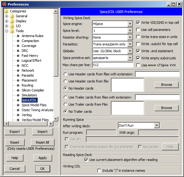
The top part of this dialog allows you to control Spice deck generation:
Note that the header and trailer information is specific to a particular technology. If you set this information for one technology, but then use another technology when generating the Spice deck, the information that you set will not be used. Note also that schematics, although a technology in Electric, are not considered to be Spice technology. You can set the proper layout technology that you want to use when dealing with schematics by using the "Layout technology to use for schematics" popup. This popup can be found in the Technology Preferences (in menu File / Preferences..., "Technology" tab, see Section 7-1-2).
The middle part of the dialog controls how Spice can be run after a deck has been written:
echo blah > file will NOT work.
Encapsulate it in a script if you want to do such things.The following variables are available to use in the program name and arguments:
The bottom part of the dialog has two controls:
Another set of controls can be used is the Spice Model Files Preferences (in menu File / Preferences..., "Tools" section, "Spice Model Files" tab). This dialog allows you to control how each cell is represented in the Spice deck.
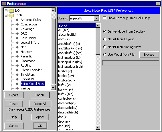
The default is to construct the Spice from the actual cell contents. If there is an equivalent layout cell, it can be used (instead of the schematic). You can also choose to use the "Verilog" view, which contains Verilog text for that cell (it will be converted to Spice). Finally, you can request that an external model file be used. Note that in the case of external model files, the specified disk file is referenced by adding "include" lines in the deck. These choices allow you to create your own definitions in situations where the derived Spice would be too complex or otherwise incorrect.
Another way to change the Spice representation of a cell is to use the Set Netlist Cell From File command (in menu Tools / Simulation (Spice)). This prompts for a file which will be included in the Spice deck instead of the actual subcircuit of the cell. The file name can be seen as a piece of text in the cell, and you can edit this text to change the desired file.
 |
Previous |  |
Table of Contents | Next |  |