
7-5-1: Introduction to Schematics
Chapter 7: Technologies
|
7-5: Schematics 7-5-1: Introduction to Schematics |
|
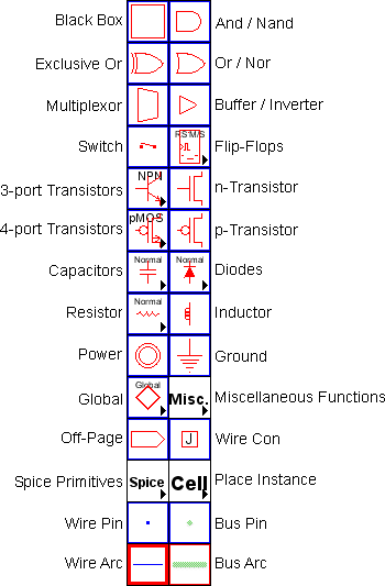 |
The Schematic technology allows you to design using digital and analog schematic components. To obtain this technology, use the popup menu at the top of the component menu and select "schematics". There are two arcs in the Schematic technology: the wire (blue) and the bus (green). These arcs can be drawn at 45 degree angles. One typically names busses with array names (for example "insig[0:7]"), and then names wires with scalar names (for example "insig[1]"). See Section 6-9-3 for more on bus naming. To make a physical connection from a wire to a bus, the bus pin can connect to either, so it acts as a tap. In addition, the Wire Con node connects wires to busses, or connects busses of different width, replicating the narrower side to make it as wide as the wider side. Use the Rip Bus command (in menu Edit / Arc) to automatically add taps to a bus. |
There are four transistor entries in the menu. The two on the right are the n and p transistors. The two images on the left are actually popup menus that let you select any style of transistor. The difference between the two on the left is that the top one is for 3-port transistors, and the bottom one is for 4-port transistors that have a substrate connection. The schematics technology understands these transistor types:
Other primitives that can appear in different forms:
The "Spice" entry presents a popup menu of Spice parts. More information about the use of these parts can be found in the Section 9-4-3.
The "Cell" entry presents a popup menu of all cell instances.
The "Global" entry provides two nodes: a "Global Signal" node defines a signal name that spans levels of hierarchy, and a "Global Partition" node allows globals to be treated locally. See Section 6-9-5 for more on global networks.
Some commands that analyze a schematic circuit need to know which layout technology will be used to fabricate the design. For example, when generating a Spice deck from a schematic, it is necessary to know the sizes and parasitics that are associated with the actual circuit. To set the layout technology to use for schematic circuits, use the Technology Preferences (in menu File / Preferences..., "Technology" section, "Technology" tab), and set the "Use scale values from this technology" popup.
Digital schematics are built with the And, Or, Xor, Buffer, Multiplexor, and Flip-Flop nodes that appear in the component menu. By attaching arcs to these components and negating them (with the Toggle Port Negation command, in menu Edit / Technology Specific), these turn into NAND, NOR, Inverter, and many other specialized components (see Section 5-4-2).
The And, Or, Xor, and Multiplexor nodes can accept any number of input connections on the left, so they require some care in wiring (see Section 1-11-5). The left side has one large input port that allows an arbitrary number of connections. Initially, wires may attach at only three input locations, spaced evenly along the left side. However, when all three locations are connected, the node automatically expands, adding additional space along the side for new arcs.
To properly wire inputs to an And, Or, Xor, or Multiplexor node, cursor placement is very important, for it determines which of the locations to use on the left side. If an arc gets connected in the wrong location, try connecting more arcs until one appears in the right place, and then delete the unwanted ones.
The Switch node can also take an arbitrary number of poles on its left side. Simply stretch it along the line of the poles and their number will grow.
The analog nodes (Resistor, Inductor, Capacitor, and Diode) have values on them which can be selected and edited. Double-clicking on them brings up a special dialog for editing their value.
The Resistor can be treated as a connecting or nonconnecting node. By default, it does not connect the networks on its two ends, and this is the correct way to treat it when doing low-level simulation such as Spice. However, for higher-level simulations (such as Verilog) the resistor should be ignored and treated as if it connects its two networks. To make this happen, use the Networks Preferences (in menu File / Preferences..., "Netlists" tab), and check "Ignore Resistors when building netlists". Note that if resistors are being ignored, Spice deck generation will temporarily include them while the netlist is being created.
 |
Previous |  |
Table of Contents | Next |  |