
2-2-2: Arc Creation
Chapter 2: Basic Editing
|
2-2: Circuit Creation 2-2-2: Arc Creation |
|
As the introductory example showed, arcs are created by clicking the right button. This can actually function in two different ways, depending on what is highlighted.
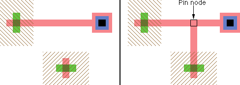
If one node is highlighted, segment wiring is done, in which an arc is drawn from the highlighted node to the location of the cursor. If there is nothing at that location, a pin is created, and it is left highlighted. Using the right button again runs an arc from that pin to another location.
By clicking and holding the right button, you can see the path that the new arc will follow. It is recommended that all wiring operations be done this way, holding the button then moving the cursor until the intended wiring is shown, and finally releasing. Wiring is quite complex and can follow many different paths, so make sure the new arc is where you want it before releasing the button.
If the cursor is over another object when the right button is released, the new wire attaches to that object. If there are multiple objects under the cursor, press the space bar (while the right button is pressed) to cycle through the possible endpoints (including the possibility of connecting to none of them). To ignore what is under the cursor and prevent the wire from connecting to anything there (making it effectively invisible), hold the control key while routing.
If you type a digit key while the right button is pressed, it changes the wiring layer by inserting contacts to that layer of metal. For example, if you are running a metal-1 wire, and type "3" during the wiring, then two contacts will be added (metal-1-to-metal-2 and metal-2-to-metal-3) to make the wire run in metal-3.
If an Unrouted arc already connects where you are placeing a new layout arc, the Unrouted arc is removed after the new one is created. This allows you to replace Unrouted arcs incrementally, one segment at a time. See Section 9-6-1 for more about Unrouted Arcs.
The other way that the creation button can operate is two-point wiring, in which two nodes are highlighted and one or more arcs are created to connect them. Highlighting of these two nodes is done by clicking the left button over the first one, and then using the shift-left button on the second. Note that if the second node is obscured by other objects, you can cycle through the objects under the cursor with the control-shift-left button. Once the two nodes are highlighted, use the right button to wire them together. Note that the highlighted ports on the selected nodes are important: arcs will run between them, so they must be compatible in their wiring capabilities.
Two-point wire creation first attempts to run a single arc. Generally, this can happen only if the ports are lined up accurately. Failing single arc placement, an attempt is made to make an "L" connection with two arcs and an intermediate node. These two arcs can bend in one of two directions, determined by the location of the cursor.
In addition to running an arc between two nodes, you can also use arcs as the starting or ending point of arc creation.
If it is sensible, the creation command actually uses one of the nodes on an end of the selected arc. However, if the connection falls inside the arc, it is split and a new node is created to make a "T" connection.
Electric will allow you to connect two nodes or arcs as long as there is some way in the current technology for those objects to be connected. For example, if connecting between metal-1 and a metal-3, Electric will place metal-1-to-metal-2 and metal-2-to-metal-3 contact, and wire between all four nodes. When such contacts are inserted, they are placed closest to the "destination" node (or farthest from the original node).
As mentioned in Section 1-8, pressing the number keys for a valid layer switches to that layer. If a node is highlighted, it will route to that layer from the node, creating contacts as necessary.
 |
Previous |  |
Table of Contents | Next |  |