
4-10-2: Preferences
Chapter 4: Display
|
4-10: 3D Windows 4-10-2: Preferences |
|
To control the 3D view, use the 3D Preferences (in menu File / Preferences..., "Display" section, "3D" tab). This provides access to most of the parameters that control 3D viewing. The only other controls available are the colors used to draw 3D features, which are available in the Layers Preferences (see Section 4-6-2).
|
In the 3D Preferences, the thickness and Z distance (height) of each layer can be controlled as well as the view mode, the Z-axis scale, and use of antialiasing. On the left side of this dialog is a list of layers in the current technology. On the right side is a cross sectional view of the chip, showing the relative position of each layer. You can select a layer by clicking on either side of the dialog. | 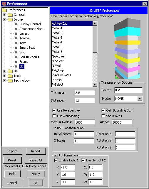 |
The currently selected layer is highlighted in the list on the left and drawn transparently in the right-hand view.
Change the "3D HIGHLIGHTED INSTANCES" entry in the Layers Preferences to change the color used for highlighting layers in the 3D view and in the preferences.
The distance of the layer from the wafer bottom and its thickness are the most important values. These values are not only used for the 3D view; they are also used whenever layers are presented in "height" order. Once selected, you can type new values into the "Thickness" and "Distance" fields.
By default, a perspective view is shown. Uncheck "Use Perspective" to see a parallel display. Antialiasing can be turned on by checking "Use Antialiasing". Due to performance issues, antialiasing is not on by default. You can also control the display of cell bounds and axes. The limit on the number of nodes prevents massively large circuits from swamping the 3D system.
The transparency option controls whether you can see through layers, allowing finer control of the display. The transparency factor ranges from 0 (fully opaque: not transparent at all) to 1 (completely transparent: an invisible shape). The transparency mode sets the rasterization technique to use during rendering. Possible values are NONE, BLENDED, FASTEST, NICEST or SCREEN DOOR. The default setting of "NONE" indicates that all objects are opaque. Due to rendering issues while setting more than 1 layer with the transparency mode "NICEST", the select layers are set with "SCREEN_DOOR" so they can be seen from any angle. Refer to jogamp.org for technical details.
Other controls are available in this dialog, for example the initial zoom factor and rotation. If the displayed layers are too thin along the Z axis (compared to their X and Y values), use the "Z Scale" field to make everything thicker.
The 3D view uses one the ambient (background) light and two directional lights. The ambient light is always on, but the directional light can be enabled or disabled with the checkboxes.
The directional lights sit outside of the circuit and point in the given direction. The default directions of (-1, 1, -1) and (1, -1, -1) illuminate the 3D view from the front. Although the lights have a default color of white, this can be changed by editing the "SPECIAL: 3D DIRECTIONAL LIGHT" entry in the Layers Preferences.
Ambient light is the background light that fills a space. It is used to illuminate those areas that are not directly hit by the directional lights. The default color of the ambient light is gray, but this can be changed by editing the "SPECIAL: 3D AMBIENT LIGHT" entry in the Layers Preferences.
| If Java3D is not installed, the distance and the thickness can still be controlled. In such a situation, the 3D Preferences dialog has much more limited information. The cross-section information on the right shows layers and their range of depth. You can choose either the layer name or its cross-section name. | 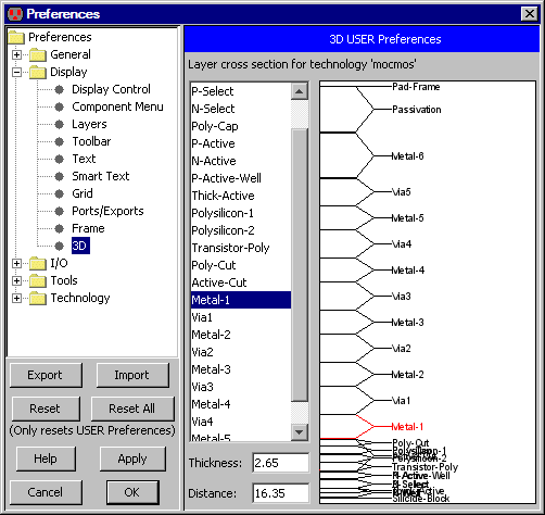 |
 |
Previous |  |
Table of Contents | Next |  |