
6-9-5: Global Networks
Chapter 6: Advanced Editing
|
6-9: Networks 6-9-5: Global Networks |
|
When wiring an IC layout, the only way to get a signal from one point to another is to physically place the wires. Signals that span a large circuit, such as power and ground, must be carefully wired together at each level of the hierarchy.
In schematics, however, it is often the case that a signal is used commonly without explicitly being wired or exported. Examples of such signals are power, ground, clocks, etc. The power and ground signals can be established in any schematic with the use of the Power and Ground nodes. To create another such signal, use the Global node of the schematics technology (see Section 7-5-1).
The Global node is diamond-shaped, and it has a name and characteristic similar to exports (input, output, etc.) All signals with the same global name are considered to be connected when netlisting occurs. Thus, the Global symbol can be used to route clock signals, as well as to define multiple power and ground rails. Note that with multiple power and ground rails, only one of them is the true "power and ground" as defined by the Power and Ground symbols. All others, declared with Global nodes, are not true power and ground signals, but are simply globals. The distinction is made by some netlisters which treat the true power and ground signals specially.
It is sometimes the case that the designer wishes to isolate a global signal and wire it differently. For example, a schematic cell may be defined with power and ground symbols, connecting it to the global power and ground. But a particular instance of the cell may need to be wired to alternate power and ground rails, for example "dirty power". Another example of rewiring happens when you want to test a specific instance of a cell, and you need to connect its globals differently for the purposes of simulation.
| The solution is to place a "Global Partition" node inside of the schematic (see Section 7-5-1). This symbol acts like an "offpage" symbol: it is wired to something inside of the cell (a global signal) and it is also exported to the outside world. | 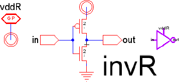 |
In this example, the schematic has power and ground signals, but the power signal is also connected to a Global Partition node and exported (as "vddR"). The icon has an extra connection for this power tap. In normal use, the extra connections created by the Global Partition nodes are not wired up, because they connect to globals, and their connectivity is understood. If, however, the extra exports are wired, it means that the signal inside of the cell is disconnected from the global, and connected instead to that wire.
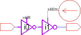 | In the example here, two "invR" icons are placed, but only one of them has its "vddR" connection wired (to a different power source). The subcircuit for the rightmost icon will not use the global power signal, but will instead use the attached signal, "vddInv". |
When writing a Spice netlist that makes use of Global Partitions, you cannot use the .GLOBAL block because it will prevent the overriding of signals. You must set the "Globals" field in Spice/CDL Preferences to "Create .SUBCKT ports" (see Section 9-4-3).
 |
Previous |  |
Table of Contents | Next |  |