 |
3-11-4: Automatic Icon Generation |
|
|
3-11-4: Automatic Icon Generation |
|
The icon cell is correctly tied to its contents in most respects. If you descend into it (with the commands in the Cell / Down Hierarchy menu), then you actually find yourself editing the associated contents cell. The Up Hierarchy command properly returns you to the location of the icon instance. Also, the network consistency checker and the simulators correctly substitute the contents whenever an icon appears. In order for this to work, however, all exports in the contents cell must exist with the same name in the icon cell (with the exception of those that are marked "Body Only").
To generate an icon cell automatically, use the Make Icon View command (in menu View). Be sure to create all relevant exports before issuing this command, so that the proper icon can be constructed. Note that any export that has its "Body only" attribute checked will be omitted from the icon.
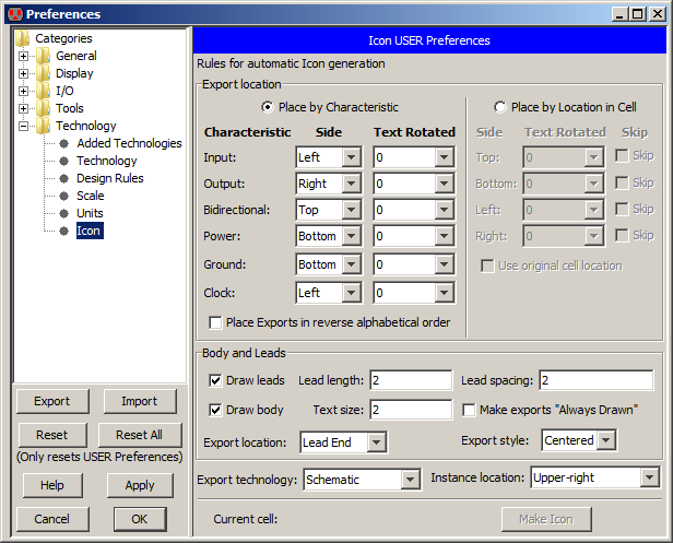
To control the look of the icons, use the Icon Preferences (in menu File / Preferences..., "Technology" section, "Icon" tab).
The top part of the dialog lets you control where exports are placed. You may choose to place them according to their characteristics (input, output, etc.) or to place them relative to their location in the original cell. When placed by characteristics, exports are arranged alphabetically around the icon, and you can choose to reverse the alphabetical order. Text can be rotated in any of four directions. When placed by location in the cell, you can set rotation on each side, ask that any side be omitted (no ports on that side) and request that the exact location of the original exports be used in the icon.
The middle section of the dialog controls the body and leads of the icon. You can choose whether or not to draw the body and leads. You can set the spacing and length of leads. You can control the size of the text used on the cell body. You can request that exports be "Always Drawn" (which means that they appear even when wired or reexported, see Section 3-6-1). You can choose the location of the exports (at the end of the leads, in the middle of the leads, or on the body). You can choose the style of the export text (whether it grows inward, outward).
The bottom part of the dialog has miscellaneous controls. You can choose the technology of the exports ("Schematic" uses nodes from the Schematic technology and can connect only to other Schematic arcs; "Universal" uses nodes from the Generic technology which can connect to any arc). You can choose the location of the "example" icon instance in the original schematic (when you use the Make Icon View command, it generates the icon and places an example instance of that icon in the schematic). One of the choices is "No Instance" which prevents placement of example icons. A button at the bottom requests that an icon be made now, and takes the place of the Make Icon View command.
 |
Previous |  |
Table of Contents | Next |  |